
Product Description
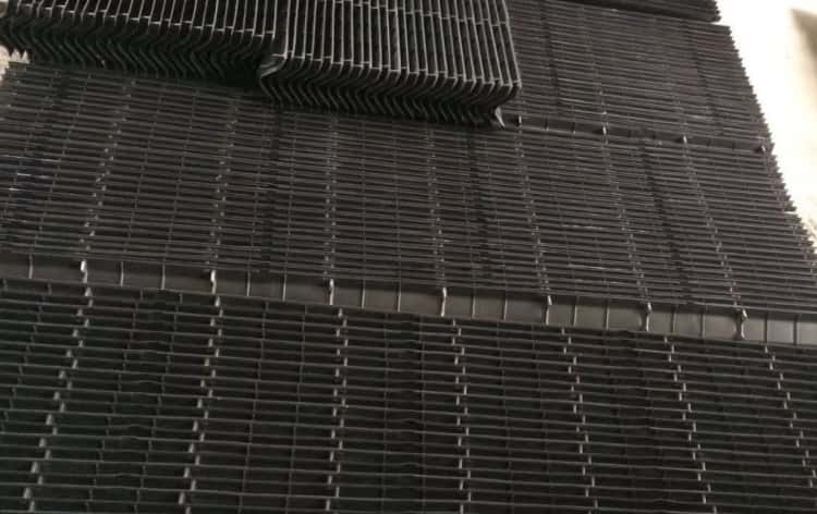
DE-080 Blade Drift Eliminator is d esigned for both counter-flow and cross-flow cooling towers, the blade type drift eliminator effectively removes entrained water droplets from the exhaust air stream while maintaining minimal pressure loss. DE-080 Blade Drift Eliminator constructed from rigid corrugated PVC sheets, the drift modules are UV protected and compatible with cooling water environments. They resist rot, fungi, bacteria, and common organic and inorganic acids and alkalis found in cooling tower applications.
The PVC sheets are made of prime rigid PVC conforming to commercial standards ASTM D1784:12344B to 12454B, with the following typical properties:
| Property | Test Method | Unit | Typical Value |
|---|---|---|---|
| Specific Gravity | D-792 | gm./cu.cm | Max 1.45 |
| Tensile Strength | D-638/D-882 | psi | Min 6000 |
| Flexural Modulus | D-790 | psi | Min 425,000 |
| Flexural Strength | D-790 | psi | Min 10,000 |
| Elastic Modulus | D-638/D-882 | psi | Min 360,000 |
| Izod Impact | D-256 | ft.lbs./in. | Min 1.0 |
| Impact Resistance | D-4226 | in.lbs./mil | Min 0.8 |
| Heat Deflection | D-648 | °F (264 psi) | Min 160 |
| Flame Spread Rating | E-84 | — | Less than 15 |
| Flammability | D-635 | — | Self-extinguishing,<5 sec |
Drift Modules Characters
- 1. The eliminators use a blade multi-pass design with end caps for enhanced structural integrity, ensuring beam strength and durability.
- 2. Each blade incorporates a deflection vane to create a horizontal air component, reducing air recirculation.
- 3. The modules can span a minimum of 6 feet under design conditions with minimal deflection.
- 4. Nesting type design ensures seamless installation and prevents drift droplet bypass.
- 5. Installed inside the tower, the eliminators limit drift to no more than 0.004% of the inlet water flow rate, guaranteed under all operating conditions.
- 6. Drift loss is measured according to CTI STD-140 HBIK drift test code or EPA Method 13A system analysis and will not exceed the 0.004% guarantee.
- 7. Materials used are suitable for continuous operation at maximum discharge air temperature.
- 8. Eliminators are made of PVC or CPVC depending on environmental temperature and are fire resistant, with a maximum flame spread rating of 15 or less per ASTM E-84, supported by certified test reports.
- 9. Drift modules measure up to 23.232 inches wide (24 blades), 4.8 inches in depth, and up to 10 feet in length.
Installation:
Installation must follow manufacturer recommendations and engineer’s specifications, including:
- A. Drift modules should be carefully cut or trimmed to fit within 1/4 inch (or less) of obstructions or sidewalls to prevent air bypass.
- B. Modules shall be transported to the top of the tower by mechanical conveyor or crane. Cranes or conveyors must be provided as needed to move the media to the working level, with final placement done manually.
- C. Shaping, cutting, and trimming may be performed inside the tower, ensuring contractors take precautions to prevent chips, broken pieces, or debris from falling into the media. Cutting may affect structural integrity.
- D. The modules are not designed to support walking personnel. Contractors should use plywood or suitable temporary planking to avoid damage or injury.
- E. Modules should be placed to achieve the closest possible fit without damage, arranged as per the cooling tower manufacturer’s recommendations and installation drawings. Sheets of all modules must be perpendicular to support beams.
Specifications:
| Blade Thickness | 0.025 in (0.64 mm) |
| Maximum Span | 6 ft (1.8 m) |
| Blade Spacing | 0.800 in (20 mm) |
| Module Depth | 5.75 in (146 mm) |
| Module Width | 24 in (610 mm) |
| Module Length | 1 to 12 ft in 1 ft increments (305 to 3660 mm in 305 mm increments) |
| Dry Weight | 6.8 lbs/ft² (32.8 kg/m²) |


